All About UART
// Brown Fine Security — Hardware Hacking Series
This is my writeup for the All About UART course by Brown Fine Security. The course is well structured and can be done in a couple of hours if you're already familiar with embedded hardware, or a solid afternoon if you're new to it like I was. I ran into a bunch of Mac-specific issues that the course doesn't cover (they advise to use linux), so I've documented all of my troubleshooting here too.
Gear
I got the Pico 2 with headers already soldered because I didn't feel like soldering for this one. Skipped the soldering session in the course for the same reason.
UART Theory
Electronic Communication Fundamentals
The course starts with voltage as information — how analog signals work versus digital signals, the difference between parallel and serial communication, and directionality of data. UART is full duplex, meaning both devices can send and receive simultaneously.
Wiring
UART uses four lines: VCC, TX (transmit), RX (receive), and GND. The key thing to remember is that TX on one device connects to RX on the other, and vice versa. Ground connects to ground.
Asynchronous Communication & Baud Rate
Unlike SPI or I2C which use a shared clock line, UART is asynchronous — there's no clock. Instead, both devices agree in advance on the timing of transmissions. This is the baud rate: the number of signal changes per second.
Common baud rates:
- 9600
- 19200
- 38400
- 57600
- 115200 — most common
Both devices must use the exact same baud rate or data will be misinterpreted. This caught me out later.
UART Data Frame
The data frame is the smallest section of data transmitted — think of it like a packet in networking. Each frame contains:
Parity is an optional error detection mechanism. With even parity, the bit is set so the total number of 1s in the frame is even. With odd parity, it's odd. Both devices must agree: none, odd, or even.
UART is referred to in shorthand as baud, databits, parity, stopbits. For example: 115200 8N1 (pronounced "eight none one") — 115200 baud, 8 data bits, no parity, 1 stop bit.
TTL vs RS-232
Most embedded devices use TTL voltage levels (3.3V or 5V). Legacy RS-232 uses different voltage ranges (e.g. -3V to -15V as logic high). Importantly, TTL devices are not resistant to different voltages — putting 5V into a 3.3V system can damage it. In those cases you need a logic level shifter.
Flashing the Pico 2
The course firmware is a .uf2 file called all_about_uart.uf2. To flash it:
- Hold the BOOTSEL button on the Pico 2
- Plug in via USB while holding the button
- Release once the drive mounts
- Copy the
.uf2file to the drive
cp ~/Downloads/all_about_uart.uf2 /Volumes/RP2350/
/Volumes/RPI-RP2. On Mac with a Pico 2 (RP2350 chip), the drive mounts as RP2350. This is correct and expected — it is in bootloader mode.
After copying, the drive disappears and the Pico reboots — that's normal and means it worked. The LED did not flash after booting, which I initially thought was an error. It's not — the all_about_uart firmware doesn't blink an LED. It just sits there waiting for a serial connection.
Logic Analyser Theory
A digital signal is binary data transformed by a serial communication protocol into voltage levels over time — an electrical signal with two states (LOW and HIGH) that changes over time to represent binary data.
Tools for capturing digital signals:
- Multimeter — too slow for serial data
- Logic analyser — just right
- Oscilloscope — great but usually overkill and expensive
On a timing diagram: the X-axis is time, the Y-axis is voltage level (HIGH or LOW). For UART specifically, the start bit is always LOW, followed by data bits, an optional parity bit, and a stop bit (usually HIGH).
Setting Up the Logic Analyser (Mac Troubleshooting)
The course uses Linux and recommends sudo apt install pulseview sigrok-firmware-fx2lafw. On Mac, apt doesn't exist — you need Homebrew. This is where things got complicated.
HiLetgo USB Logic Analyser
The HiLetgo 8-channel analyser uses a Cypress FX2 chip and is driven by the fx2lafw firmware — one of the best supported devices in sigrok.
Attempt 1: Homebrew PulseView
brew install pulseview
Attempt 2: Pre-built .app from sigrok.org
Downloaded the macOS binary from sigrok.org. Hit two missing library errors in a row:
Library not loaded: /usr/local/opt/python@3.12/...
Library not loaded: /usr/local/opt/dbus/lib/libdbus-1.3.dylib
Fixed by installing the missing dependencies:
brew install python@3.12
brew install dbus
After that, PulseView opened but showed nothing — running from terminal revealed a Python version mismatch. The app bundle had Python 3.13 paths hardcoded but was looking for 3.12 stdlib. Not fixable without rebuilding.
Attempt 3: DSView
Switched to DSView (by DreamSourceLab), which is a maintained fork of PulseView with proper macOS builds. Downloaded the .dmg from dreamsourcelab.com.
DSView opened fine, but the HiLetgo didn't appear in the device list. Checking the terminal output revealed the cause:
sr: dslogic: Scan DSLogic device... Found: 0
sr: dscope: Scan DSCope device... Found: 0
Attempt 4: Sigrok-CLI + Build PulseView from Source
brew install sigrok-cli
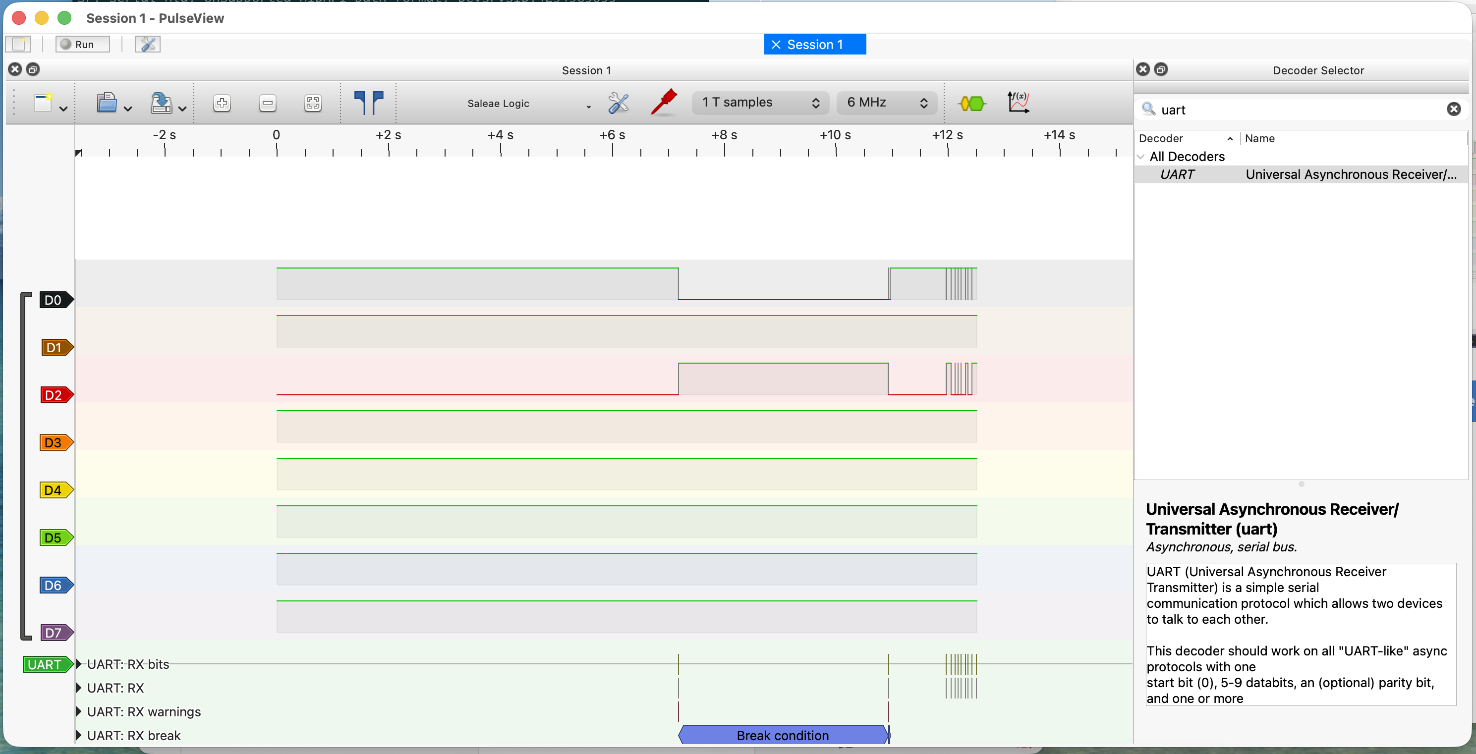
sigrok-cli --scan
# fx2lafw - Saleae Logic with 8 channels: D0 D1 D2 D3 D4 D5 D6 D7
Built PulseView from source against local Homebrew libraries:
brew install cmake pkg-config libsigrok libsigrokdecode \
  glib glibmm@2.66 libusb boost qt@5
git clone https://github.com/sigrokproject/pulseview.git
cd pulseview && mkdir build && cd build
cmake .. -DCMAKE_PREFIX_PATH="$(brew --prefix qt@5)" \
         -DCMAKE_BUILD_TYPE=Release
make -j4
Hit three compile errors due to API changes in newer library versions. Fixed them by patching the source:
storesession.cpp—Glib::DateTimevsGlib::TimeValmismatchdecodesignal.cpp—SRD_OUTPUT_LOGICremoved in libsigrokdecode 0.5.3decoder.cpp—srd_decoder_logic_output_channelstruct removed in libsigrokdecode 0.5.3
Connecting to the Pico via Serial
The course uses various terminal tools. On Mac, the simplest that worked for me was miniterm via pyserial.
pip3 install pyserial --break-system-packages
python3 -m serial.tools.miniterm /dev/cu.usbserial-AB9BHU7G 115200
To find your port name first:
ls /dev/cu.*
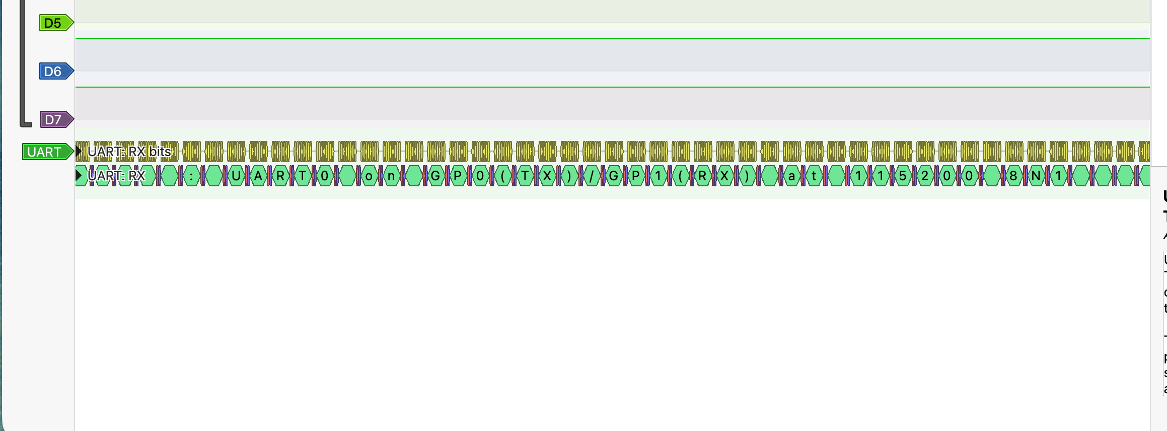
Look for something like /dev/cu.usbserial-XXXXXXXX. Once connected you should see the firmware's password prompt.
pico2 — enters the main menu with options 1–5.
To quit miniterm: Ctrl+]
The Challenge — Brute Forcing the UART PIN
*ALERT* There are spoilers beyond this point, proceed at your own risk
The main menu has an Unlock option (option 4) that prompts for a 3-digit PIN. The task is to brute force it using a Python script over serial.
The course provides a starter script. The two changes needed for Mac:
# Change 1: Update the port name (Linux uses /dev/ttyUSB0, Mac is different)
port='/dev/cu.usbserial-AB9BHU7G',

# Change 2: Match the correct baud rate
baudrate=115200,
Close miniterm first (only one program can hold the serial port at a time), then run:
python3 brute.py
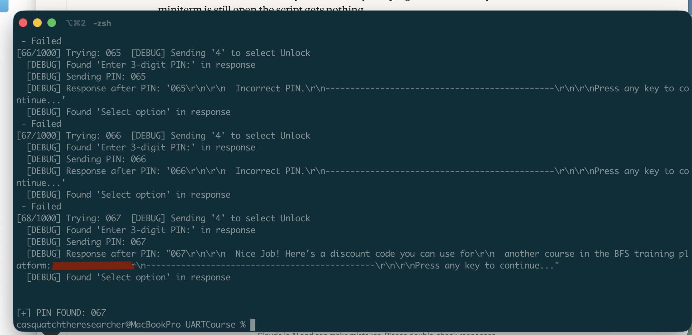
The script loops through every PIN from 000 to 999, sends each one via the Unlock menu, and checks if the response contains "Incorrect PIN". If that phrase is absent, the PIN was accepted.
Password: prompt on startup. If the Pico already booted before the script connected, it missed it. Fix: unplug and replug the Pico right after starting the script.
Why This Matters
This is a great demonstration of why UART security matters on real hardware:
- PINs should never be hardcoded in firmware
- Rate limiting is essential — without lockout after failed attempts, brute force is trivial
- UART debug ports on production devices should be disabled or physically removed
- An attacker with physical access and a $10 USB-to-UART adapter can do exactly what we just did